 The young earth's molten surface was in constant motion, like the lava in an active volcano today. As a solid crust began to form, it was carried about on the surface by the moving magma beneath. Although this crust has grown thicker and stronger over time, it is still in motion atop the moving mantle.
The crust is divided by a world-wide system of faults, trenches, and mid ocean ridges into six major plates and many minor plates that fit together like the pieces of a jigsaw puzzle, as you can see on the image.
These plates, however, move and change shape. In some places, they slide past one another; in others, they collide or move apart. The theory that explains how these processes work to shape the crust is called plate tectonics. apart. The theory that explains how these processes work to shape the crust is called plate tectonics.
The earth's surface consists of two kinds of crust. Oceanic crust is thin (about 5 to 7 miles) and dense. The rock that makes up the continents, however, is thick (10 to 30 miles) and relatively light. A continent rises high above the surrounding oceanic crust and extends deeper into the mantle-like an iceberg in a frozen-over sea.
 Sometimes a plate splits and begins moving apart. This is the way ocean basins are formed. The picture on the left shows a rift forming in the middle of a continent. As the two parts of the continent pull away from each other, magma rises from the mantle and solidifies in the gap, forming a mid ocean ridge. New crust being thinner but denser than the continents spreads outward between the two "daughter" continents. The Atlantic Ocean was born in just this way about 200 million years ago when North and South America split away from Europe and Africa. Sometimes a plate splits and begins moving apart. This is the way ocean basins are formed. The picture on the left shows a rift forming in the middle of a continent. As the two parts of the continent pull away from each other, magma rises from the mantle and solidifies in the gap, forming a mid ocean ridge. New crust being thinner but denser than the continents spreads outward between the two "daughter" continents. The Atlantic Ocean was born in just this way about 200 million years ago when North and South America split away from Europe and Africa.
Where plates meet head on, several things can happen. If oceanic crust meets oceanic crust, one plate is subducted that is, it slips beneath the edge of the other plate and descends into the mantle, forming a trench in the ocean floor. The descending plate is melted by the hot mantle in the subduction zone. Some of its minerals melt at lower temperatures than others and rise through the crust as magma, which may either cool and solidify within the crust, forming igneous rock such as granite, or reach the surface as volcanic lava.
If one of the converging plates is made up of continental crust, it overrides the heavier oceanic plate, which bends downward in a trench along the continental margin. When this happens, magma from the descending plate may erupt in continental volcanoes like Mount St. Helens. If both of the plates are continental, the collision buckles and folds the rocks including the sedimentary rocks at the edges of the continents-into great mountain ranges like the Himalayas.
 Geologists now obtain close estimates of the age of rocks by measuring their radioactivity. Naturally occurring radioactive elements, such as uranium, change at a measurable rate into other elements, such as lead. By measuring the proportions of different forms of lead, scientists can tell about how much time has passed since a rock was formed. Using such methods, geologists have radically changed our ideas about the age of the planet.
Even the ten million years that it took to carve the Grand Canyon is but the most recent moment of geologic history. The earth was formed about 4.6 billion years ago when frozen particles and gases circling a new yellow star were brought together by mutual gravitational attraction. Heated by compression and radioactivity, this material formed a molten sphere.
The heaviest components, mostly iron and nickel, sank to the center and became the earth's core. Lighter minerals formed a thick, molten mantle, while minerals rich in aluminum, silicon, magnesium, and other light elements cooled and solidified into a thin, rocky crust./span>
The surface of the young planet was an inhospitable place. Molten rock (magma) erupted everywhere through fissures and volcanoes, expelling the gases and water vapor that formed the early, oxygen less atmosphere. As the surface cooled, rain condensed and fell in torrents, and the first oceans began to form.
The earth was devoid of life for perhaps its first billion years. Eventually, out of a mixture of complex carbon-chain chemicals, the first self-replicating molecules appeared in the ocean, perhaps in the muck of some shallow lagoon. Over millions of years these primitive organisms grew more complex and varied, first as single-celled bacteria like forms, later as microscopic protozoa and algae. Some grew in the form of colonies, which over further millions of years evolved into more complex organisms. As photosynthetic single-celled plants, which used carbon dioxide and gave off oxygen, became more abundant, their waste oxygen became a major constituent of the atmosphere. photosynthetic single-celled plants, which used carbon dioxide and gave off oxygen, became more abundant, their waste oxygen became a major constituent of the atmosphere.
Few traces of this early life survive, however. Although plant remains and impressions of primitive organisms can be found, it was about 4 billion years before animal life became abundant enough (and developed body parts durable enough) to leave significant numbers of fossils. This early, fossil-poor period, comprising most of the time since the earth formed, is commonly known as the Precambrian era.
The last 600 million years of earth's history comprise the time of abundant life. The first fish appeared about 500 million years ago in the early Palaeozoic era, followed by the first land plants, amphibians, and reptiles. The Mesozoic (220 to 65 million years ago) was the era of the dinosaurs, early mammals, and primitive birds. And the Cenozoic era embraces the time from the extinction of dinosaurs through the recent ice ages to the present.
 Here on the right you can see a cross section of Earth illustrating the core; mantle and crust. The enlarged position shows the relationship between the lithosphere, composed of the continental crust, oceanic crust and upper mantle and the underlying asthenosphere and lower mantle. Here on the right you can see a cross section of Earth illustrating the core; mantle and crust. The enlarged position shows the relationship between the lithosphere, composed of the continental crust, oceanic crust and upper mantle and the underlying asthenosphere and lower mantle.
And on the left, have a look at the cross section of Earth showing the various layers and their average density. The crust is divided into a continental and oceanic portion. Continental crust is 20 to 70 km thick, oceanic crust is 5 to 10 km thick.
 Let us have some talk about the offshore exploration of the hydrocarbons, i.e. oil and gas, in general. We are so happy to introduce the series of articles shedding some light on this interesting subject.
The readers will get to know so much more about the basic geology for a start, and after that we will start diving deeper and deeper in the drilling equipment and technology, from the very beginnings and up to such modern types as directional drilling. All systems and machinery pieces on board rigs will be explained in detailed, with the supporting images and videos, whenever required.
Spend some time reading these articles and make sure you have checked all of them, and we promise that you will see that your knowledge and understanding of the drilling technology and associated equipment and techniques has sufficiently expanded.
In the petroleum industry, which finds and recovers oil and gas from deep within the earth's crust, geology is fundamental. Petroleum occurs mostly in isolated, hard-to-find accumulations. The scientific study of the earth's history and its life, especially as recorded in the rocks of the crust, reduces the risk of drilling dry holes and lowers the cost of production by helping determine the most efficient way of drilling a well.
Knowledge of geology increases the total supply of petroleum by helping recover more of the resource in place. Petroleum geologists are most concerned with rocks formed in the earth's surface by processes closely associated with both climate and life. The way these rocks are created and changed, as well as how oil and gas form and accumulate in them, are the principal concern of the petroleum geologist. For a thorough understanding of these processes, it is necessary to look back in time-first, to the beginning of the modern science of geology; then, to the beginning of the earth itself.
Ancient geologists believed that the earth had been created all at once, complete with all its mountains, canyons, and oceans, in a single great cataclysm. In the 1700s, though, scientists began to understand that familiar natural processes, such as the accumulation and erosion of sediment, and "minor" cataclysms, such as earthquakes and volcanic eruptions, could account for all the features of the earth's crust-given enough time. Thus the doctrine of catastrophism was eventually supplanted by the theory of gradualism or uniformitarianism meaning, as Scottish geologist James Hutton put it two centuries ago, that "the present is the key to the past."
This concept of gradual change is central to modern geology. Today's geologists know that the Grand Canyon is the work of a powerful erosive agent, the Colorado River, over some ten million years, as you can see on the picture; that the Himalayas and the Sierra Nevada are growing loftier by a fraction of an inch each year, and have been doing so for millions of years; that Africa and America are moving away from each other about as fast as a fingernail grows.
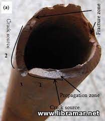 When drilling through H2S environments, sulfide stress cracking SSC – a form of hydrogen embrittlement – is a frequent cause of drill stem failure. Both stress and the absorption of hydrogen in the presence of sulfide are involved in this type of failure.
Atomic hydrogen, the smallest of atoms, is a product of most corrosion reactions. It can be absorbed by and diffused through steel and other metals. Normally, the hydrogen atoms quickly combine to form molecular hydrogen, which is too large to be absorbed by the metal and bubbles off as gas. In the presence of sulfide, however, the hydrogen remains in the atomic form for a considerably longer time and therefore has a greater probability of being absorbed by the pipe. After being absorbed, the hydrogen tends to accumulate in the area of maximum stress and, when a critical concentration is reached, a small crack forms. The hydrogen accumulates at the top of the crack and the crack grows. The process continues until the remaining metal cannot sustain the applied load and a sudden brittle fracture occurs.
The degree of this effect on a piece of steel is determined by the concentration of hydrogen, the strength of the steel, applied stress on the steel, and the time of exposure:
Strength of the steel – generally, the higher the strength of the steel, the greater is its susceptibility to SSC. The lowest strength drill pipe capable of withstanding the required drilling conditions should be used.
Total tensile load on the steel – the higher the total tensile load on the pipe, the greater is the possibility of failure by SSC. Each grade of steel has a critical, or threshold, stress below which SSC will not occur; however, the higher the grade, the lower the threshold stress.
Amount of atomic hydrogen and H2S – the higher the amount of atomic hydrogen and H2S present, the shorter the time before failure.
Time – it is required for atomic hydrogen to be absorbed and diffused in the steel to the critical concentration required for a crack to begin and failure to occur. By controlling the factors in the previous three listings, the time before which failure occurs may be sufficiently lengthened to permit the use of marginally susceptible steels for a short duration.
Temperature – the severity of SSC is greatest in normal atmospheric temperatures; it decreases as temperature increases. Operating at temperatures in excess of 135 F allows marginally susceptible materials to be used in potentially embrittling environments. The greater the hardness of the material, the higher the required safe operating temperature. Drillers must be careful, however, because SSC failure may occur when the material returns to normal temperature after it is removed from the hole.
In order to minimize the risk of SSC in water-based drilling fluids, drillers should control the drilling fluid pH. When practical, given other functions of the drilling fluid, the driller should maintain a pH of 10 or higher. In drill strings containing aluminum drill pipe, the pH should not exceed 10.5 because aluminum pipe tends to corrode more than steel at high pH level. They should also limit gas-cutting and formation fluid invasion of the wellbore by maintaining proper drilling fluid weight. Hydrogen sulfide invades the wellbore from the formation being drilled.
The drillers should also chemically treat the drilling fluid for H2S inflows from formations, preferably prior to encountering the sulfide, and use the lowest-strength drill pipe capable of withstanding the required drilling conditions, use ultimate care in tripping out the hole after exposure to an H2S environment and avoid sudden shocks and high load.
It is also recommended to remove the absorbed hydrogen from the pipe after exposure to an H2S environment by aging the pipe in open air for several days to several weeks, depending on the exposure conditions, or bake it at 400-600 F for several hours. Note that the plastic-coated drill pipe should not be heated above 400 F.
Finally, the drillers should limit drill stem testing in H2S environments to as brief a period as possible, using operating procedures such as using H2S inhibitors that will minimize exposures to SSC conditions.
Corrosion and SSC can be minimized by the use of oil-based drilling muds. Corrosion does not occur if metal is completely enveloped by an oil environment that is electrically nonconductive. Therefore, under drilling conditions that cause serious problems of corrosion damage, erosion-corrosion, or corrosion fatigue, drill stem life can be greatly extended by using an oil mud.
 Surface imperfections in the drill pipe metal greatly affect the fatigue limit of the metal. Imperfections can be mechanical or metallurgical. A notch or pit concentrates the stresses encountered during drilling and speeds the breakdown of the metal structure. They are, therefore, referred to as stress risers, or stress concentrators. Where the notch or pit appears on the drill pipe determines how much it will affect the fatigue limit of the pipe. If a notch is on a portion of drill pipe not subject to stress, the notch has little effect. If a notch is within twenty inches of a tool joint in the pipe’s upset runout, where maximum bending takes place, it can form the nucleus of an early fatigue break.
The shape and type of notch or scratch is also important. A longitudinal notch, an extensive saucer with a rounded bottom, will distribute the stress and be relatively harmless whereas a minute scratch with a sharp bottom will act as a stress riser and lead to failure.
Some steel is more sensitive to notches as other steel; notched brittle steel fails more quickly than ductile steel. Various surface dents and scratches that can cause eventual drill pipe failure include the tong marks and slip marks, cuts, scratches, spinning chain marks and scratches, stencil markings, hammer marks, corrosion grooves caused by rubber protectors, electric arc burns, and downhole notching caused by formation and junk cuts. dents and scratches that can cause eventual drill pipe failure include the tong marks and slip marks, cuts, scratches, spinning chain marks and scratches, stencil markings, hammer marks, corrosion grooves caused by rubber protectors, electric arc burns, and downhole notching caused by formation and junk cuts.
Of all these defects, tong marks although rare, are probably the most damaging marks produced on drill pipe in the field. They are long, deep, and frequently sharped. Because such notches are longitudinal, they may not lead to notch failure. Even a slight deviation from vertical in the wellbore, however, can change the stress on the pipe and longitudinal notches can become stress concentrators. A change in the wellbore from vertical alters the stress along the defect from longitudinal to transverse. Tongs, therefore, should be applied to the tool joint, never to the body of the drill pipe, because the toll joint is thicker than is the pipe itself. In addition, applying tongs to drill pipe body may crush the pipe as well as notch it.
Rotary slips are made with fine serrations and are used to hold the pipe in place and to prevent it from slipping down into the hole when a connection is being made or broken out. The slips can, however, score the pipe if they are mistreated, worn, or carelessly handled. Slips with worn, mismatched, incorrectly sized, or improperly installed gripping elements can allow one or two teeth or portions of the teeth to catch the full load of the drill string, thereby causing deep notching and potential failure.
 Inasmuch as any transverse mark can be a dangerous stress concentration point, it is not surprising that steel stencil marks can be the start of fatigue when parts of the letter are transverse to the pipe and the steel stamp is in the wrong place. Never steel stencil on the drill pipe tube. Inasmuch as any transverse mark can be a dangerous stress concentration point, it is not surprising that steel stencil marks can be the start of fatigue when parts of the letter are transverse to the pipe and the steel stamp is in the wrong place. Never steel stencil on the drill pipe tube.
Corrosion at the top of the rubber pipe protectors can produce a circumferential groove. These grooves can lead to failure. Modern protectors are designed to minimize this risk. Because the protectors usually produce the grooves when they are left on the pipe while the pipe is in storage, the IADC recommends removing them before placing pipe in storage.
Welders sometimes attach the ground lead to the pipe rack instead of to the material being welded. This action is particularly dangerous in that the subsequent arcing between the rail and the drill pipe goes unnoticed. This arcing pits the pipe. Though these pits are small, they are surrounded by a wide band of burned metal that is as hard as glass and they are very prone to rapid fatigue failure.
It is very important that the drilling crew not run bent or crooked pipe into the hole. A crooked joint of pipe is always a potential failure. A crooked Kelly can cause bending in the first joint of drill pipe below the rotary table. If the stress is great enough, failure will occur. Having a crown block off center because the mast or derrick is not plumb can also cause pipe failure because the off-center block throws bending stresses into the Kelly and the drill string.
 Unlike drill collars, the drill string is not ordinarily used to put weight on the bit. The drill string is made of steel or aluminum and is normally used for two basic purposes: to serve as a conduit, or conductor, for the drilling fluid; and to transmit the rotation of the rotary table or top drive to the bit on the bottom. Since it is not exclusively used to put weight on the bit, the drill string is smaller and lighter than the drill collars. In addition, in straight-hole drilling, it is suspended in the hole under tension, not compression. It is kept in tension by two opposing forces – the weight of the collars pulling it from the below and the hoist, line, and blocks pulling on it from the surface. Keeping the drill string in tension prevents it from bending and buckling and prolongs its life.
Manufacturers design the drill string so that it can withstand some of the most common stresses encountered during drilling. Relative to a drill collar, the drill string is small and thin, yet it can withstand powerful forces. Basically, the drill string is a column, or string, or drill pipe with attached tool joints. Most drill pipe is steel that is forged into a solid bar and then pierced to produce a seamless tube. Because the wall of the tube is relatively thin, usually less than half-inch thick, the manufacturer cannot cut threads into it. To solve the problem of providing threaded ends, so that the pipes can be screwed together, manufacturers produce tool joints.
The tool joint is a separate piece of metal welded onto a seamless drill pipe to produce the characteristic bulge at each end. The wall of the tool joint is thick enough to have the pin or the box cut into it. To prepare the drill pipe for welding, the manufacturer first heats the ends of the pipe and then strikes the heated end forcefully. These heavy end-on blows thicken the hot steel in the pipe ends. Manufacturers call the thickened ends “upsets”. The pipe maker thickens the last 3 to 6 inches of each end of the pipe to make it stronger.
 Each piece of drill pipe, excluding the tool joint, may have an outside diameter ranging from 2 3/8 to 6 5/8 inches (6.03 centimeters to 16.83 centimeters). Not only does the OD of drill pipe vary, but also the length of the pipe. Manufacturer make drill pipe in one of three API-recommended ranges of lengths. Range 1 lengths vary from 18 to 22 feet (5.49 to 6.71 meters). If a pipe measures, for example, 20 feet (6 meters) long, it would be range 1 length. Range 2 lengths fall within 27 to 30 feet (8.23 to 9.14 meters). Range 3 lengths are from 38 to 45 feet (11.58 to 13.72 meters).
Manufacturers produce these three ranges of lengths because derrick heights vary. The drilling contractor must be able to buy drill pipe lengths that make into stands of a height that fit inside the derrick. He drilling crew needs plenty of height above the stand to be able to manipulate it in the derrick. The most commonly used length of the drill pipe is the range 2 length. Most derricks are from 125 to 150 feet (38.1 to 45.2 meters) which allows a three-joint stand of 30-foot (about 9-meter) joints to fit into the derrick.
Manufacturers produce drill pipe according to API specifications concerning yield and tensile strengths. Minimum yield strength refers to the specific value at which the pipe will permanently distort. Minimum tensile strength refers to a specific value at which the pipe will snap, or pull apart. Drilling contractors determine what type drill pipe they need based on the conditions they expect to encounter downhole. The depth of the hole is the primary factor for determining what grade is needed. Other factors include whether or not the hole is straight or directional and the type of formations being drilled.
 Corrosion is the alteration and degradation of material caused by its environment. Corrosion fatigue, or metal failure due to a corrosive environment, is a common cause of drill stem failures. With water-based drilling fluid, the chief corrosive agents of drill pipe are dissolved gases, such as the oxygen, carbon dioxide, and hydrogen sulfide, as well as dissolved salts, and acids.
Most modern drill pipe is made with a thermally baked plastic coating applied to the inner surface to minimize corrosion pitting. Wirelines and tools in the drill string bore tend to rupture or destroy the plastic coating that protects the pipe.
Among the many factors affecting corrosion rates of drill pipe are the following:
pH – it is a scale for measuring the hydrogen ion concentration of a particular environment. The pH scale is logarithmic; that is, each pH increment of 1.0 represents a tenfold change in hydrogen ion concentration. The pH of pure water is 7.0. pH values below 7 are increasingly acidic, and pH values greater than 7 are increasingly alkaline.in the presence of dissolved oxygen, the corrosion rate of steel n water is relatively constant between pH 4.5 and 9.5. The corrosion rate increases rapidly at lower pH values and decreases slowly at higher pH values. In drilling, the pH level rarely falls below 7. Most problems occur at pH levels between 7 and 10.5.
Temperature – in general, corrosion rates increase with increasing temperature.
Velocity – in general, corrosion rates increase with higher rates of fluid flow through the pipe.
Heterogeneity – in general, the more uniform the grain structure of a pipe, the less will be the corrosive effect of the environment. Localized variation in the composition of microstructure of the metal – that is, corrosion in small, well-defined areas – may increase the corrosion rates.
High stresses – highly stressed areas may corrode faster than areas of lower stress. The highest bending stresses occur in doglegs, where the tension is highest. doglegs, where the tension is highest.
Corrosion can take many forms and may combine with other destructive processes – erosion, abrasive wear, and notch failures – to cause severe damage. Several forms of corrosion may occur at the same time, but one type will usually predominate. The following forms of corrosion are most often encountered with drill pipe:
Uniform, or general attack – in this type of corrosion, the pipe corrodes evenly, usually leaving a coating a corrosion products, i.e. iron oxide, or rust;
Pitting, or localized, attack – in this type of corrosion, the pipe corrodes in small, well-defined areas, causing pits to form. These pits may vary in number, depth, and size; they may also be obscured by corrosion products. A drill stem inspection crew can detect pitting with magnetic inspection. Pits can serve as points of origin for fatigue cracks and lead to washouts. A washout is a place where a small opening has occurred in the pipe, usually as a result of a fatigue crack’s penetrating the pipe wall and allowing drilling fluid through it;
Corrosion fatigue – in a corrosive environment, no fatigue limit exists, since failure will ultimately occur from corrosion, even in the absence of cyclic stress. The cumulative effect of corrosion and cyclic stress is greater than the sum of the damage from each. The endurance limit, or fatigue threshold, will always be lower in a corrosive environment, even under mildly corrosive conditions that show little or no visible evidence of corrosion.
|