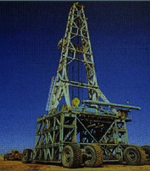
 Let us spend a couple of minutes on the land-based oil rigs. Yes, most of the materials and information presented herein are related to the offshore units; however, it would make sense to know a bit about how this all started. Just read this short article.
As we know, the very first drilling rigs used were land rigs and were invented and subsequently both in Texas, USA and in Germany just over hundred years ago.
Nowadays, the land-based oil rigs constitute an advanced piece of machinery and when thinking of the amount of engineering and care in manufacturing, racing cars can look a bit sedate.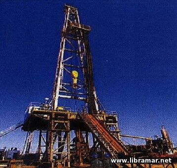
Land rigs come in all sizes, from small trailer mounted rigs to very large rig systems requiring more than 100 trucks to move. One of the first criteria for design of a land rig is how to move it. If the rig has to move on normal roads, it has to be dismantled to pieces that can be easily be transported by truck and does not exceed axle load restrictions.
In addition to weight limitations, the sizes of equipment that has to be moved will also impose problems and cost. In most countries, there are rules for height and width of goods to be transported on roads. When exceeding these rules, police escort and road and bridge modifications may add significantly to the overall cost of drilling a well.
Rigs dedicated for work in deserts are quite often built without regards for road transport. Some of the EDC, standing for the Egyptian Drilling Company, rigs working in Syria and in Egypt have large wheel assemblies, or moving gears retrofitted so the entire Rig with mast and substructure can move in one piece.
 This is quite a reduction in loads to move and makes quite a difference in the time it takes to move the rig. If it takes seven days to move a rig without the moving gear attached it will take approximate sixty hours for the rig move with the moving gear attached. This is quite a reduction in loads to move and makes quite a difference in the time it takes to move the rig. If it takes seven days to move a rig without the moving gear attached it will take approximate sixty hours for the rig move with the moving gear attached.
Land rigs have a distinct advantage over rigs made for working on water, space and weight is not a problem. Contractors build rig sites to suit the rig and the equipment not the other way around. A standard desert foot print for a rig location is 400 ft x 400 ft.
Another advantage is that if a project requires special equipment this can be added to the rig inventory without worrying about deck loads and permissions. Also, note that a rig may require additional mud tanks for a well and this will then be no problem as land locations can be expanded easily enough.
Newer land rigs are also designed for fast rig up and rig down as well as minimizing the impact on the landscape and environment. Drive past a pad of producing wells today and there will hardly be anything to evidence that a big rig and a large rig location has been in use. All that can be seen is a few square meters of concrete where the wellhead is located and safely fenced in.
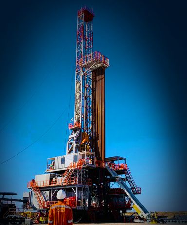 Although this section of our website is devoted to the offshore exploration and drilling activities, this short article is here to cover the major types of oil rigs in general.
Oilfield drilling is, when it comes down to bare essentials, a question of “drilling a usable hole” in the ground. And, in turn, usable hole is commonly characterized by being a hole in the ground that lives up to the requirements of the well-plan and includes benchmarks for production, cost and lifespan.
The main pieces of equipment required to drill a hole in the ground is collectively known as a drilling rig. Drilling rigs are classified according to what the rig is supposed to be standing on when it drills and how it is moved around. The main media to stand on is land and water.
It is pretty simple, but that is how it is.
Land rigs are made for working on solid ground where no special requirements are necessary except the area to be flat and of a certain size. All other rigs are made for working either over water or floating in the water. There are barges and jack-up type rigs which are made to stand on the seabed on the bottom of the water and/or swampland and marshes, and there are semi submersibles and drill ships that float in the water. Each type will be described separately on the next pages. It is important to notice that in general, the main drilling equipment on all these rigs are the same. The difference is how it moves and where the drilling location is situated.
There are other sub-types of drilling rigs that are not specifically described here. These rig types include:
• Heli-Rigs, or Helicopter transportable land rigs, these are made mostly of aluminum,
• Dedicated coiled tubing rigs,
• Slanted drilling rigs, used for the Slant hole drilling ,
• HDD, utility drilling rigs, normally hydraulic-driven.,
Most of them use the same type of equipment to drill and most of the processes are very similar with the exception of coiled tubing drilling systems.
In this lecture on drilling equipment, the focus will be put on the drilling rig and its related equipment. The method of drilling the hole is subject for a different lesson.
Some types of equipment are used on all types of rigs, basically the drilling equipment, and other equipment is rig type-specific, i.e., to be able to compensate problems inherent in the rig design or use.
When looking at different drilling rig types and different locations around the world, all drilling rigs consist of the same basic equipment with the same functions, all over the world. A giant concrete platform rig in the North Sea area with 800 people onboard is essentially doing the same as a humble land rig in east Texas. The same types of equipment and people perform just about the same jobs. Of course, the food is more readily available on the big platforms and they have galleys, television rooms and many other recreational facilities to keep the crew occupied while waiting to go back to work.
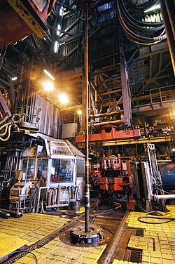 The rig floor is the business end of the drilling machine. It is the place where the drilling operation is controlled and where accidents and disasters can be prevented. The rig floor area is under the command of the Driller, the most important person on a drilling rig, because he is the person with the hands on the controls for the drilling machine and also receives alarms and signals from the well directly on his various control panels. The Driller is in charge of the rig crew. He reports to his supervisors which is the Tourpusher and Toolpusher.
A lot of planning is included when building a new drilling rig. The result is often an improvement over existing rigs. When a rig floor is designed there is often collaboration between Drillers, Rig Owner, Engineers and other people with a vested interest in the success of the project.
The layout must consider a number of criteria, including “must do” and “must not do” as well as “need this” and “got to have that”. It is like designing a dream home, everything has to fit perfectly and compromises are only acceptable in the small claims department.
The main elements on and around the rig floor include:
• Doghouse – The drillers control room, where all the main controls for the rig floor area is located.,
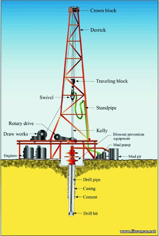
• Drawworks – the power winch that lift or lower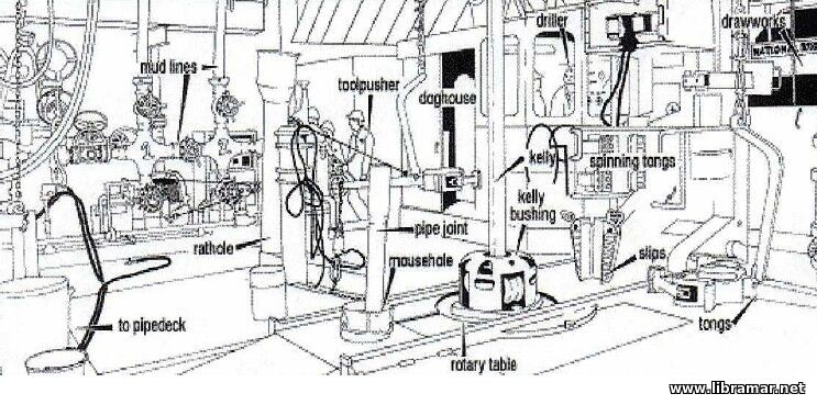 s drill string into the well. Part of hoisting system which includes mast or derrick, Drill line, Crown block with sheaves, Travelling block with sheaves and finally the drill line and anchor., s drill string into the well. Part of hoisting system which includes mast or derrick, Drill line, Crown block with sheaves, Travelling block with sheaves and finally the drill line and anchor.,
• Derrick/Mast – Supports all the weight of the drill string and allows lengths of pipe to be lifted or lowered into the well and allows racking of lengths of tubular to be racked (stored) in stands when not in use.,
• Rotary table – Where the drill string enters the hole and where slips and other tools are used to suspend drill string and add or reduce number off tools to be run into the hole.,
• Pipe handling equipment – “Automatic” addition or removal of stands from drill string sometimes including stand building capacity.,
• Iron Roughneck – Machine used for Make-up or break-out of tubular in the drill string. Removes the dangerous use of manual operation with rig tongs.,
• Rig tongs (Manual) – Manual tong used for make-up or break-out of tubular in the drill string.,
• BOP control panel – Where the Driller controls the Blowout Preventer Stack. It allows the Driller to close-in the well.,
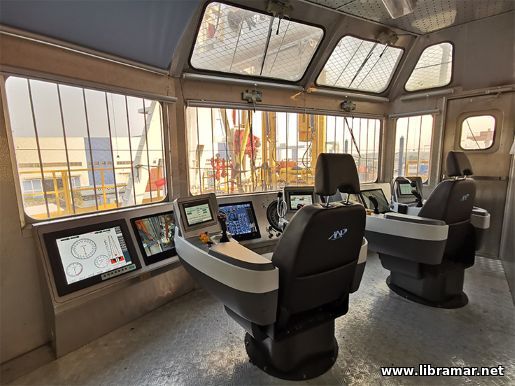 There are quite a few instruments for the Driller to observe and control and quite a few of the instruments/gauges and buttons seems to be added to the initial set-up giving the overall impression of the cabin as being cluttered and confusing. This is unfortunately quite often the picture of a Drillers Cabin, or Dog house. All sensors and data required for the driller are available on the two screens. There are quite a few instruments for the Driller to observe and control and quite a few of the instruments/gauges and buttons seems to be added to the initial set-up giving the overall impression of the cabin as being cluttered and confusing. This is unfortunately quite often the picture of a Drillers Cabin, or Dog house. All sensors and data required for the driller are available on the two screens.
The concept of operating a drilling rig entirely just by two joy-sticks and two screens can be a challenge to the older generation of drillers. They do not like to rely solely on a computer manufacturer to make all the rig safety devices work. Especially when talking about well control equipment (BOP). But this is the future and it creates even higher demands on rig crew competencies than ever before.
Rig crews in the future must be multi-skilled specialists trained to work with and maintain special equipment and tools not seen in any other industry. Additional equipment usually placed on the rig floor or in the immediate vicinity includes:
• Air winches – Winches either air- or Hydraulic driven with a load range approx. 10000 lb. used for lifting pipe to the rig floor from the pipe deck or used for lifting heavy things around on the rig floor or even for lifting and hang off equipment in the Derrick. One type of air winch must also be available on the rig floor and this is a winch which must be used for lifting personnel and only be used for this purpose.,
• Standpipe manifold – A system of valves piping and connections used for routing drilling fluid piped up from pump room to standpipe(s) in the Derrick into the mud hose (Kelly hose) through the swivel and down the drill string.,
• Choke manifold – A system of valves piping and connections used in well control situations where BOP is closed and mud and well bore fluids coming from the well (Annulus) are routed from the BOP up the choke line to the choke manifold and then through the choke and the Mud/gas separator where gas is removed from the mud and then over shale shaker and to the mud process tanks.,
• Pipe rack – Racking area on the pipe deck. On a land rig special racks are built so that pipe can be rolled right onto the catwalk and the hoisted to the rig floor. Horizontal pipe storage area for pipe or casing.,
• Catwalk – Movable walkway where pipe is landed when removed from rig floor to pipe deck storage or vice versa. This walkway is also attached to the V-Door ramp which is the slide coming from rig floor towards pipe deck.,
The rig floor has to accommodate all these tools and equipment and it is even more complicated by the fact that electrical systems may have to be explosion proof. This includes making the equipment electrically safe and spark proof to prevent accidental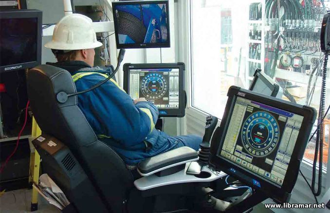 fires and explosions if gas or oil leaks out of the well. EX proofing is expensive and under stringent requirements and special training is required for electricians working with this type of equipment. fires and explosions if gas or oil leaks out of the well. EX proofing is expensive and under stringent requirements and special training is required for electricians working with this type of equipment.
It is an amazing engineering feat to see the complex jumble of high-pressure piping, air lines, mud hoses, hydraulic hoses/piping and electrical wiring fitted underneath the rig floor and terminating up through the rig floor in just the right place.
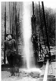 Ever since man started to dig holes in the ground, searching for salt, fresh water and minerals, there has been a continuous development. In digging technology, the first wells were dug by hand and as one got deeper, the wells were lined with rocks and wood to prevent them from collapsing.
When entering the oil-bearing zones, fumes and gases started to interfere with “digging”. It became necessary to drill rather than dig and this was the start of the oil drilling industry.
All types of drilling, whether it is for water, minerals or oil, have to abide the laws of physics. It is therefore no coincidence that most of the drilling techniques developed in the different areas of the world, are quite similar. Although a mining rig looks very different from and oil drilling rig, they perform the same function, namely “drilling a usable hole”. Drilling for oil and gas successfully is a process that requires a number of skills and a lot of advanced equipment. As the drilling process becomes more complicated, the drilling tools and the way they are used, must also be updated.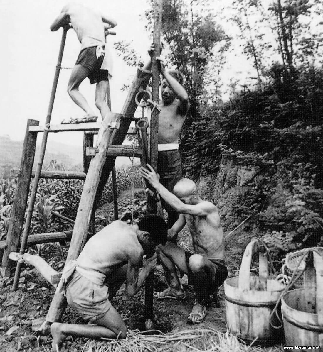
The oil industry began over five thousand years ago. In the Middle East, oil seeping up through the ground was used in waterproofing boats and baskets, in paints, lighting and even for medication.
Whale oil has been used in more recent times as a source of light in houses. However, the high premium for whale oil decimated whale populations and as their numbers dropped the prices rose further.
The demand for oil was now far higher than the supply. Many companies and individuals were looking for an alternative and longer lasting source of what would later become known as black gold. Apart from a brief period of coal oil, the answer came with the development of drilling for crude oil. Land oil wells were first and as demand continued to grow exploration companies began to look below the sea bed.
The first oil well structures to be built in open waters were in the Gulf of Mexico. They were in water depths of up to 100m and constructed of a piled jacket formation, in which a framed template has piles driven through it to pin the structure to the sea bed. To this, a support frame was added the working parts of the rig such as the deck and accommodation. These structures were the fore-runners for the massive platforms that now stand in very deep water and in many locations around the world, including the North Sea. How did they know to look for oil beneath the North Sea? In 1959 the massive Groningen land gas field was discovered in the Netherlands. Geologists estimated that the same rock formations might be found beneath the southern North Sea basin in UK 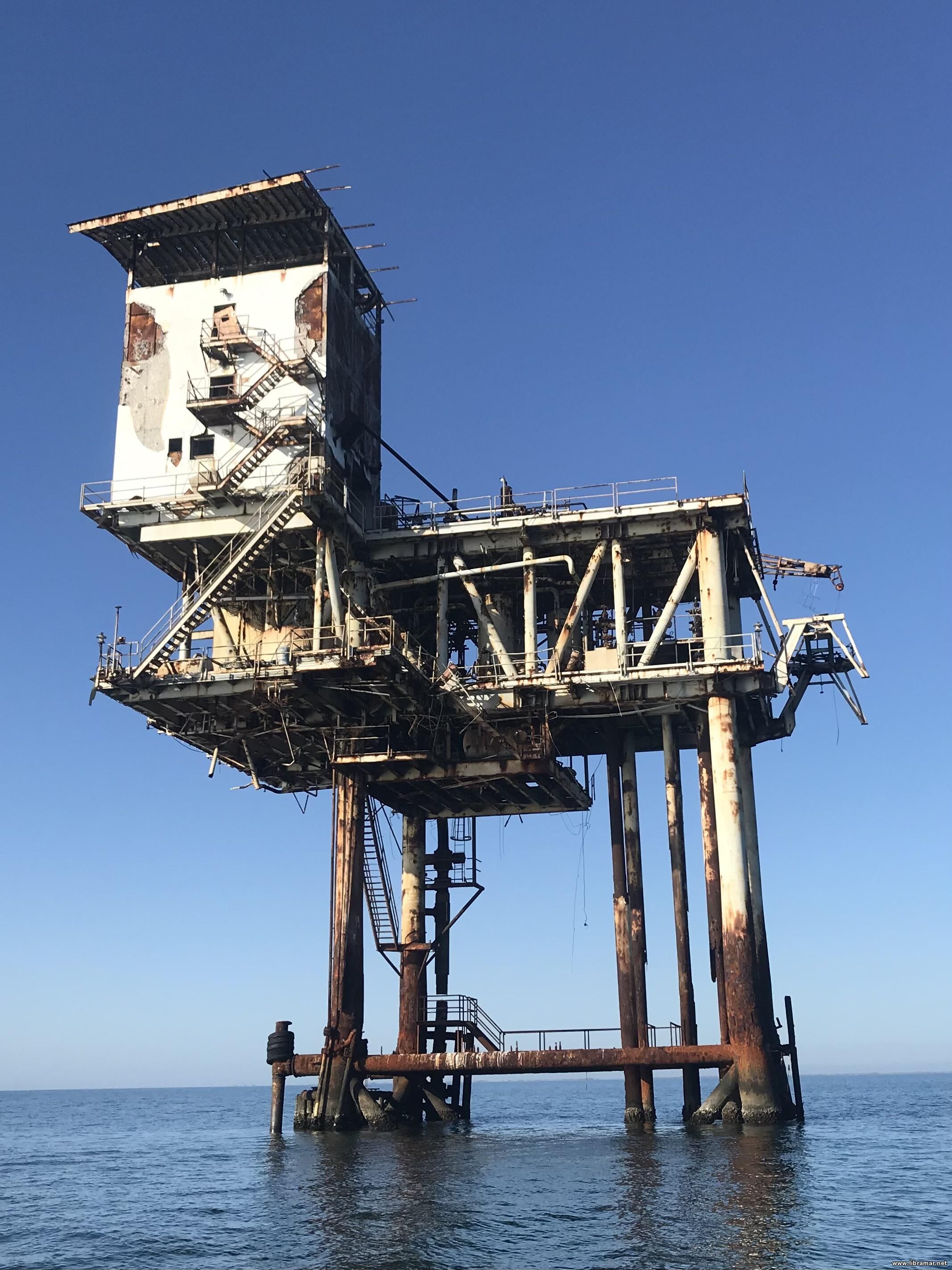 waters. They were right and gas was discovered of the English East Coast in the 1960s. waters. They were right and gas was discovered of the English East Coast in the 1960s.
Clues around the coast of Greenland gave Geologists the idea that there may be oil and gas around Scottish waters.
There have been land oil wells in Europe since the 1920s. It wasn't until the 1960s that exploration in the North Sea really begun, without success in the early years. They finally struck oil in 1969 and have been discovering new fields ever since. The subsequent development of the North Sea is one of the greatest investment projects in the world.
The development of the offshore oil industry in hostile waters has been made possible by many achievements comparable with the space industry. Many fields are located far from land and they are getting further away. New fields are being explored in ever deeper and wilder waters, like the Atlantic Ocean west of Scotland.
After the North Sea UK disaster in 1988 when on 6 July, the North Sea Piper Alpha oil platform caught fire and exploded killing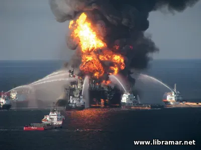 167 of the 228 on board. The industry and the government waited until 1990 for the publication of the Cullen report. Lord Cullen discovered that the main cause of the explosion was the failure in the operation of the permit to work system, for which there are now very strict guidelines. This system is used to over-sea work, preventing potentially dangerous work being carried out. It also prevents dangerously conflicting work being carried out by a combination of workers and it ensures that proper laid down procedures are adhered to. The report brought about many changes and a journey towards much greater safety awareness, procedures and regulations. 167 of the 228 on board. The industry and the government waited until 1990 for the publication of the Cullen report. Lord Cullen discovered that the main cause of the explosion was the failure in the operation of the permit to work system, for which there are now very strict guidelines. This system is used to over-sea work, preventing potentially dangerous work being carried out. It also prevents dangerously conflicting work being carried out by a combination of workers and it ensures that proper laid down procedures are adhered to. The report brought about many changes and a journey towards much greater safety awareness, procedures and regulations.
Today the industry is very safety conscious. It has to be for its very survival. For example, the safety record of an exploration rig can make a big difference to whether or not an oil company will want to hire it. Oil companies cannot afford to have their name associated with accidents.
When you first arrive, you are given a tour of the installation, detailing all safety aspects including fire extinguishers, emergency muster stations, lifeboat stations and procedures. You will be introduced to the rig safety programme.
Everyone attends weekly safety meetings and daily pre "tour" meetings. The weekly meeting is an in-depth look at industry wide safety news and other safety related issues on the rig. Companies share safety information with other companies throughout the industry. This helps to avoid repeated incidents. A fire and boat drill are often held on the same day which involves a mock fire and a mock abandon the rig exercise. The pre-tour meeting is usually a description of the work carried out when you are off shift, the work you will be doing, the work others are currently doing that may affect you and any other relevant issues of the day.
Accidents do happen as in every industry. However, statistics show that with the massive improvements in offshore safety procedures, you now have a higher chance of having an accident if you work on a building site than you do on an oil rig.
Petroleum or crude oil is an oily, flammable liquid that occurs naturally in deposits, most often found beneath the surface of the 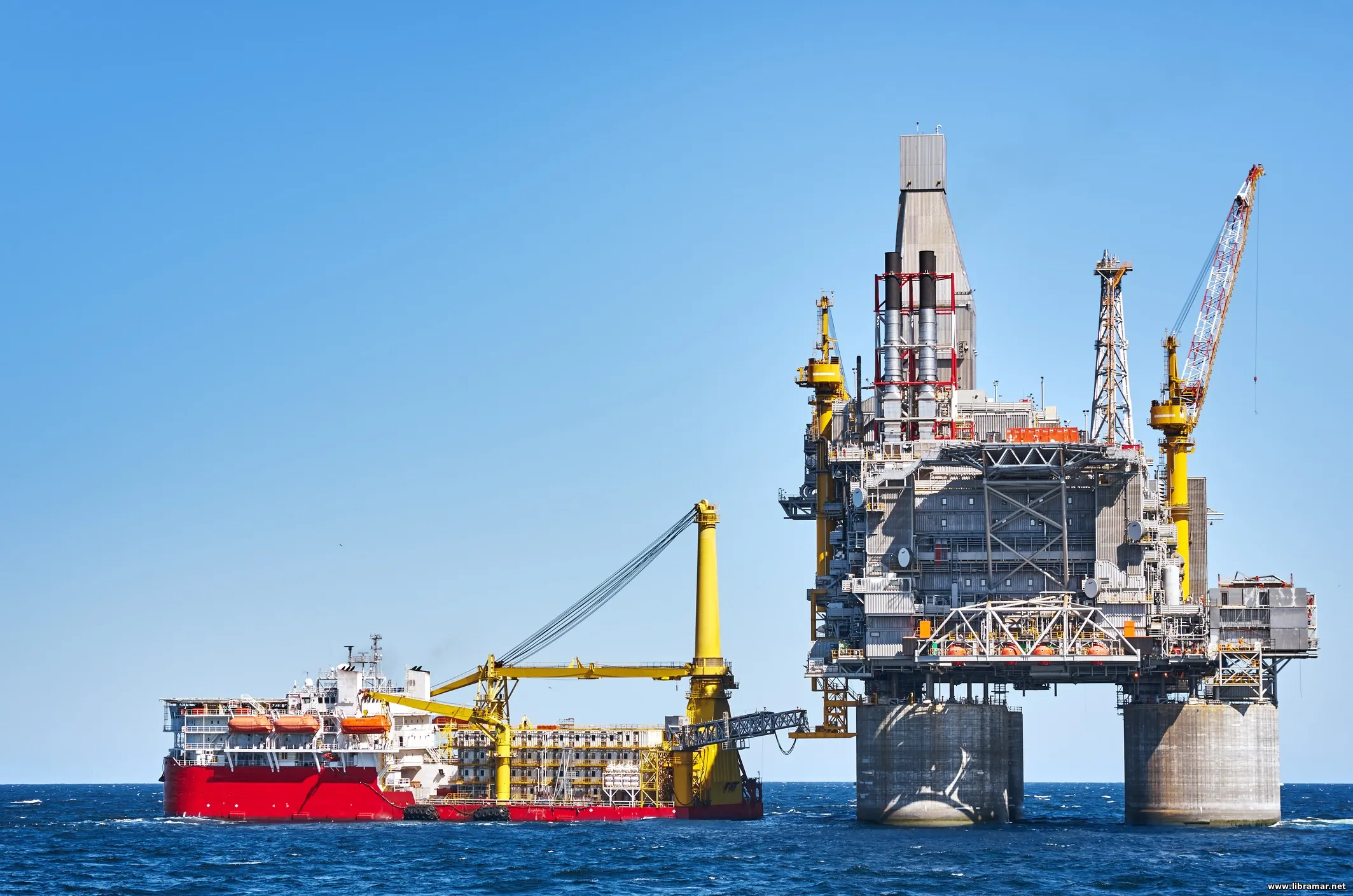 earth. Over millions of years, plant and animal remains fall to the floor of shallow seas. As the seas recede, the plant material is covered by sediment layers, such as silt, sand, clay, and other plant material. Buried deep beneath layers of rock, the organic material partially decomposes, under an absence of oxygen, into petroleum that eventually seeps into the spaces between rock layers. As the earth's tectonic plates move, the rock is bent or warped into folds or it "breaks" along fault lines, allowing the petroleum to collect in pools. Man was not unfamiliar with crude oil. In the Middle East, seepages and escaping petroleum gases burned continuously, giving rise to fire worship. It was also used for building mortar, roads, in a limited way for lighting, but was primarily used for healing everything from headaches to deafness. It was also used in war, for obvious reasons. earth. Over millions of years, plant and animal remains fall to the floor of shallow seas. As the seas recede, the plant material is covered by sediment layers, such as silt, sand, clay, and other plant material. Buried deep beneath layers of rock, the organic material partially decomposes, under an absence of oxygen, into petroleum that eventually seeps into the spaces between rock layers. As the earth's tectonic plates move, the rock is bent or warped into folds or it "breaks" along fault lines, allowing the petroleum to collect in pools. Man was not unfamiliar with crude oil. In the Middle East, seepages and escaping petroleum gases burned continuously, giving rise to fire worship. It was also used for building mortar, roads, in a limited way for lighting, but was primarily used for healing everything from headaches to deafness. It was also used in war, for obvious reasons.
 Primary well control barrier
During normal drilling operation it will always be the hydrostatic pressure of the drilling fluid that creates the primary barrier to avoid any flow of formation fluid into the well bore. If for any reason the primary barrier is lost the well control equipment together with the drilling fluid in the well bore will be the secondary barrier. This will allow us to re-establish the primary barrier on a safe and efficient way.
Secondary well control barrier
The well control equipment must be able to close and secure the well under all circumstances. Further to that circulation of heavy drilling fluid into the well bore and formation fluid out of the well bore under controlled manner must be possible.
The well control equipment should be able to close on open hole, meaning without tubular, around the bottom hole assembly, BHA for short, and other tubular used in the drilling operation. It should also be able to cut the drill string or lighter tubular and seal the well bore and allow the drill string to be hanged off on the pipe rams or stripped into the well bore.
To avoid single components to create total failure of the system a contingency, i.e. back up function should be built into the system.
All well control equipment must be maintained, function- and pressure tested according to company policy and procedures to assured correct function and integrity when required.
With the well closed in and the drill string in the well bore, formation pressure can be obtained through the drill string by adding shut-in drill pipe pressure, or SIDPP, with pressure hydrostatic.
To secure the drill string and obtain integrity following barriers can be used:
• FOSV, standing for the full opening safety valve,
• One way valves (IBOP, Dart sub),
• Check valves (Drill pipe floats).
To secure the annulus and obtain integrity following barriers can be used:
• Annular Preventer,
• Ram Preventer,
• Shear/Blind Ram,
• Rotating head.
During normal drilling operation two barriers must always be in place where the hydrostatic head of the drilling fluid is one and the BOP’s the other
 When establishing an oil or gas well, it is not enough just to drill a hole from the surface down to the hydrocarbon layer. The hole must be cased with steel pipes that are duly cemented to the formation in order to make sure than no undesirable event, such as formation fluids entering the hole, and causing blowout take place in the process of drilling. This is one of the key aspects of all drilling programs.
It is very important for anyone engaged in the drilling process to have clear and deep understanding of the casing, what it consists of and how it functions. This is what we have tried to cover below in this mini-article. You are highly encouraged to go through the listing carefully and make sure equal attention is given to each item.
These casings have several important functions of which the following can be named:
• To prevent the hole being washed out in weak formations or collapsing.
• Prevent lost circulation.
• Control the formation pressure, where the density of the drilling fluid (mud) is not heavy enough to control the formation pressure. This can be the case, if one has just drilled through a high pressure zone, set a casing and after that have reduced the mud weight to drill the next type of formation.
• Control the production from the oil / gas bearing formation.
• Prevent water from entering the production zone.
• Make the installation of tubing possible, and production test equipment and other equipment that is necessary to achieve an effective production (seals, pumps etc.).
• Isolate the mud and the hole wall mechanically from each other to prevent fluid loss from the mud to the formation. prevent fluid loss from the mud to the formation.
• Reduce the friction forces that are present. Especially important with directional drilling.
• Function as a foundation for the BOP and thereby make pressure control possible.
Casing are named after the different tasks they have to perform, here they are named in the order they are inserted:
• Surface casing.
• Intermediate casing.
• Production casing.
• Liner.
Conductor pipe
Conductor is the first casing. It is often a 30’’ pipe placed in a 36’’ hole at a depth of 150 feet to 500 feet under the seabed. With jack up rigs it is often hammered in and is also called a drive pipe.
The purpose of this casing is to ensure the return of the drilling fluid, while at the same time prevent the loose formations on and below the seabed in collapsing into the hole. It is also the foundation of the permanent casing frame when drilling from a floating rig, and is often constructed with extra wall thickness in the top.
Surface casing
Surface casing can be a 20’’ pipe placed in a 26’’ hole at a depth of from 1000 feet to 3000 feet, depending on local conditions. This should line the hole down to a depth where the formations are enough compacted and strong enough to exert the necessary forces, if a BOP is closed in connection with pressure control, as the casing is the foundation for the BOP.
 The casing should reach down to a formation that is sufficiently strong to hold the pressure from a drilling fluid, with sufficient density to control the formation pressure down the next casings setting depth. The surface casing should also isolate possible shallow pockets of gas. The casing should reach down to a formation that is sufficiently strong to hold the pressure from a drilling fluid, with sufficient density to control the formation pressure down the next casings setting depth. The surface casing should also isolate possible shallow pockets of gas.
Intermediate Casing
Intermediate casing can be 16’’ pipe, but it is often a 13-3/8’’ and a 9-5/8’’ pipe with setting depths down to 11.000 feet or more, but all depending of weights. The more intermediate casings there are, the less the internal diameter of the last set. This will result in a reduced production rate from the well. Intermediate casings are set to isolate weaker formations, so the formation pressures further down can be controlled with an increased drilling fluid density. In addition they must cover the pressure difference between the formation strength and the formation pressure, which are necessary to control a possible kick with a closed BOP.
When drilling directional, drill string can cause serious damage on the casing. A smaller diameter casing can be necessary in a production well, just before a change in direction, as it will be easier to get a thinner pipe through the bent part of the hole. In certain cases, the casing is not going right up the surface, but is hanged off with the help of a casing-hanger, 100 - 300 feet up in the previously set casing. This is because of economic reasons. This casing is called a liner. If the liner afterwards is connected up to the surface, then a connection can be made with a so-called Tie back assembly cases, the casing is not going right up the surface, but is hanged off with the help of a casing-hanger, 100 - 300 feet up in the previously set casing. This is because of economic reasons. This casing is called a liner. If the liner afterwards is connected up to the surface, then a connection can be made with a so-called Tie back assembly
Production casing
Production casing is the last set casing. This comes from the reservoir and up to the well head, but in, some cases it is hanged off in the last intermediate casing and is called the production liner.
The production casing should form a sealed connection between the reservoir and the wellhead, and protect the production equipment against pollution from outside, and make it possible to control the well, when the production assembly is retrieved for work over etc. The production casing forms a barrier between reservoir and the production equipment, so the reservoir fluid can be controlled through the perforations and possible gravel or sand packing.
 The composition of the drilling fluid and control of its properties concern every member of the drilling crew because they affect the safety of the workers as well as the success of the drilling operation. How well the composition of the fluid meets well requirements is determined only by performance in the hole. If the fluid fails in some essential function, the composition can be altered to bring about the needed change in properties, provided the relationship between function, composition, and properties is recognized.
The nature of a suspension such as drilling fluid is that fine particles of solid materials are mixed throughout a liquid medium.
In water-base drilling fluids, water is the medium. It is said to be the “continuous phase”. The particles, such as clay, shale, barite, and other solids-are said to be the “dispersed phase”. That part of the drilling fluid in which particles are dispersed so finely as to be invisible when viewed through an optical microscope is called the colloidal, or reactive, fraction. Solids such as sand that remain inactive in the dispersion are referred to as the inert, or non-reactive, fraction. The control of water-base fluids deals mainly with the colloidal fraction, because it is the portion that can be enriched by the addition of clays, improved by chemical treatment, or damaged by contamination. damaged by contamination.
Clays can be defined in a number of ways, but their important characteristic, for drilling mud purposes, is the ability to absorb water and hydrate, or swell. The gelling and swelling qualities of clays give drilling fluid properties that make them different from other viscous liquids such as honey or lubricating oil. This tendency to hydrate, which is greater in some clay than in others, determines whether chemical treatment is needed to achieve the properties desired for a particular drilling situation.
Bentonite, commonly used colloidal clay, is predominantly montmorillonite, a clay mineral that disperses into small particles in water and hydrates, increasing viscosity and reducing filtration. Native clays, on the other hand, usually hydrate only slightly; when added to a fluid, they tend to remain inert, increasing the viscosity of the mud only slightly. Clay yield refers to the number of barrels of drilling fluid with a viscosity of 15 centipoises (cp) that can be obtained from 1 ton of material. The defining value for yield is 15 cp because the critical part of the clay yield curve for all types of mud appears at that point. Additions of clay up to 15 cp promote little viscosity.
Other useful information about a mud can be obtained by considering its clay constituents. For example, about 20 pounds per barrel (lb./bbl.) of bentonite is required to produce a 15-cp viscosity drilling fluid. Such a fluid would contain 6 percent solids by weight, yield 90 bbl./ton, have 2.5 percent solids by volume, and weigh about 8.6 pounds per gallon (ppg).
 The quality of the water used to make up and maintain water-base drilling fluids affects the way fluid additives perform. Clays have the greatest yield in distilled water. Hard water - water that contains large quantities of calcium (Ca) and magnesium (Mg) salts - and brine waters reduce clay yield, usually resulting in poor mud performance. If the makeup water is salt water (having 10,000 or more parts per million [ppm] sodium chloride), native clay and Wyoming bentonite will lose a significant portion of their gelling and viscosity producing properties, and salt water clay may be substituted. Saltwater clays are composed chiefly of attapulgite, which gels and develops viscosity in saturated salt water in much the same way as bentonite does in fresh water. The quality of the water used to make up and maintain water-base drilling fluids affects the way fluid additives perform. Clays have the greatest yield in distilled water. Hard water - water that contains large quantities of calcium (Ca) and magnesium (Mg) salts - and brine waters reduce clay yield, usually resulting in poor mud performance. If the makeup water is salt water (having 10,000 or more parts per million [ppm] sodium chloride), native clay and Wyoming bentonite will lose a significant portion of their gelling and viscosity producing properties, and salt water clay may be substituted. Saltwater clays are composed chiefly of attapulgite, which gels and develops viscosity in saturated salt water in much the same way as bentonite does in fresh water.
An understanding of the viscosity characteristics of clay-water mud is extremely important in drilling mud control. Good mud properties can be maintained only by controlling the concentration and quality of low-gravity solids. Solids picked up by the mud during drilling cause mud-treating problems. These drilled solids seldom provide adequate colloidal properties for good mud control; therefore, the nature of the solids already in the mud must be determined before treating the mud.
 In discussing the components of the earth's crust, it is important to distinguish between rocks and minerals. A mineral is a naturally occurring crystalline substance of a definite range of chemical composition. A rock is a mixture of minerals, usually in the form of grains that may be easily visible or microscopic. The most common rock minerals are silicates-crystalline compounds composed largely of silicon in chemical combination with aluminium, magnesium, oxygen, and other common elements.
Igneous rocks are those that cool and solidify from a molten state. They are classified by chemical composition and grain size. These characteristics, in turn, depend on the elements present in the magma and on how long they cool-the longer the cooling time, the larger the crystals.
Rocks that are exposed at the surface of the earth are subject to weathering by climatic agents, especially water. Water breaks down solid rock by changing it chemically, by dissolving some of its minerals, by supporting the growth of plants and animals that grow on and around rock, and by freezing and expanding to wedge the rock apart. Running water then carries fragments of rock and soil to sedimentary basins-low places where sediments can accumulate, sometimes to a depth of several miles. The weight of the accumulating sediments compresses and bonds the deeper beds into layers of sedimentary rock.
Any type of rock that is buried deeply enough or otherwise subjected to great pressure, stress, or heat can become transformed both chemically and physically into another kind of rock: metamorphic rock. For instance, shale, a crumbly sedimentary rock made of clay, can be changed by heat and pressure into hard metamorphic slate. Slate, or any other rock, can in turn be heated until it melts and then cooled into fresh igneous rock, or it can be broken down by weathering so that it contributes to the formation of new sedimentary rock. The principles involved in the transformation of one type of rock into another are illustrated by the rock cycle.
Two of the most important characteristics of sedimentary rocks, attributes that are rarely found in igneous and metamorphic rock, are their porosity and permeability.
Porosity is the amount of empty space present within the rock; it is usually expressed as a percentage of total rock volume.
Permeability is a measure of the ease with which a fluid flows through the connecting pore spaces of a rock; the more connections between pores, the higher the permeability.
Porosity and permeability are of supreme importance to the geologist in determining whether a body of rock can contain petroleum and whether that petroleum can be extracted and brought to the surface.
|